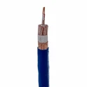
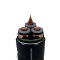
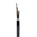
As a trusted supplier of Screened Control Cables, ensuring the integrity of our products is of utmost importance. Screened control cables are widely used in various industries, including automation, telecommunications, and power distribution, to transmit control signals while protecting them from electromagnetic interference (EMI). In this blog post, I will share some effective methods to test the integrity of a Screened Control Cable.
Visual Inspection
The first step in testing the integrity of a Screened Control Cable is a thorough visual inspection. This can reveal obvious signs of damage such as cuts, abrasions, or kinks in the cable jacket. A damaged jacket can expose the internal conductors and shielding to environmental factors, which may lead to signal interference or even electrical shorts.
Inspect the cable connectors as well. Loose or corroded connectors can cause poor electrical contact, resulting in signal loss or intermittent operation. Check for any signs of overheating, such as discoloration or melting, which may indicate a high - resistance connection.
Continuity Testing
Continuity testing is a fundamental test to ensure that the conductors within the cable are intact. You can use a multimeter set to the continuity mode for this purpose.
- Isolate the Cable: Before testing, make sure the cable is disconnected from any power sources to avoid electrical shock.
- Test Each Conductor: Connect one probe of the multimeter to one end of a conductor and the other probe to the corresponding end of the same conductor at the opposite end of the cable. If the multimeter beeps or shows a very low resistance (close to zero), it indicates that the conductor has continuity. Repeat this process for each conductor in the cable.
- Check for Shorts: While testing the continuity of each conductor, also check for shorts between different conductors. Connect one probe to one conductor and the other probe to a different conductor. A low - resistance reading between two conductors indicates a short circuit, which is a serious issue that needs to be addressed.
Insulation Resistance Testing
Insulation resistance testing measures the resistance of the insulation material between the conductors and the shielding or between different conductors. A high insulation resistance value indicates good insulation, while a low value may suggest insulation damage.


- Use an Insulation Resistance Tester: Also known as a megger, this device applies a high - voltage DC signal to the cable and measures the resulting current. The insulation resistance is then calculated using Ohm's law (R = V/I).
- Prepare the Cable: Ensure that the cable is clean and dry before testing. Disconnect all devices connected to the cable and short - circuit all the conductors at one end of the cable.
- Perform the Test: Connect the megger to the short - circuited conductors and the shielding or to different conductors as required. Apply the test voltage for a specified period (usually 60 seconds) and record the insulation resistance value. Compare the measured value with the manufacturer's specifications. A value significantly lower than the specified value may indicate insulation degradation.
Shielding Integrity Testing
The shielding of a Screened Control Cable plays a crucial role in protecting the signals from EMI. Testing the integrity of the shielding is essential to ensure its effectiveness.
- Continuity of the Shield: Similar to conductor continuity testing, use a multimeter to check the continuity of the shielding. Connect the probes to different points along the shielding to ensure that it forms a continuous path.
- Shielding Effectiveness Testing: This is a more complex test that measures the ability of the shielding to reduce EMI. Specialized equipment such as a spectrum analyzer and a shielded test chamber may be required for this test. The cable is placed in the test chamber, and a known EMI signal is applied. The level of EMI on the conductors inside the cable is then measured and compared to the level of the applied EMI. A high shielding effectiveness indicates that the shielding is working properly.
Capacitance Testing
Capacitance testing can provide valuable information about the physical and electrical properties of the cable. Changes in capacitance can indicate issues such as moisture ingress, insulation damage, or improper cable installation.
- Use a Capacitance Meter: Connect the capacitance meter to the conductors of the cable according to the manufacturer's instructions. Measure the capacitance between different conductors or between the conductors and the shielding.
- Compare with Specifications: Compare the measured capacitance values with the manufacturer's specifications. Significant deviations from the specified values may indicate problems with the cable.
Dielectric Withstand Testing
Dielectric withstand testing, also known as hipot testing, is used to determine the ability of the cable's insulation to withstand high - voltage stress without breaking down.
- Use a Hipot Tester: Connect the hipot tester to the cable and apply a specified high - voltage AC or DC signal for a set period (usually 1 minute).
- Monitor for Breakdown: During the test, monitor the current flowing through the cable. If the current exceeds a pre - set limit, it indicates a breakdown in the insulation. A breakdown can be caused by insulation defects, such as voids or cracks.
Testing Specific Types of Screened Control Cables
- 10*2 Control Cable: The 10*2 Control Cable is a commonly used type of screened control cable. When testing this cable, pay special attention to the continuity and insulation resistance of the 10 pairs of conductors. The shielding should also be tested thoroughly to ensure effective EMI protection.
- Copper Screened Control Cable: Copper Screened Control Cable offers good conductivity and EMI shielding. However, copper is prone to oxidation, which can affect the shielding performance. During testing, check for signs of oxidation on the copper shielding and ensure its continuity.
- Aluminum Shielded Control Cable: Aluminum Shielded Control Cable is lightweight and cost - effective. When testing this cable, be aware that aluminum can form a thin oxide layer, which may affect the electrical contact. Ensure that the oxide layer is removed when making connections for testing.
Conclusion
Testing the integrity of a Screened Control Cable is a comprehensive process that involves multiple steps and tests. By performing these tests regularly, you can ensure that the cables are in good working condition, minimize the risk of signal interference, and extend the lifespan of the cables.
If you are in need of high - quality Screened Control Cables or have any questions about cable testing, please feel free to contact us for procurement and further discussions. We are committed to providing you with the best products and services.
References
- Electrical Installation Handbook, Schneider Electric
- Cable Testing Manual, Megger
- Standards for Control Cables, International Electrotechnical Commission (IEC)